


What buyers should verify first
Realistic tolerance depends on the feature, material, datum scheme, setup and inspection method. General milling at plus or minus 0.05 mm is commonly economical, while selected controlled features can reach plus or minus 0.01 mm when the process and gauging justify it.
| Review area | What good control looks like | Buyer action |
|---|---|---|
| General untoleranced dimensions | Use a stated general standard agreed on the drawing | Avoid verbal assumptions |
| Critical bores/shafts | Can be tighter with controlled finishing and gauging | Confirm process capability |
| True position/profile | Datum scheme and fixturing dominate | Review setup plan |
| Thin walls | Distortion can exceed machine positioning error | Plan stress and clamping |
| Finished surfaces | Coating growth may change final dimensions | Define before/after finish |
1. Separate machine accuracy from process capability
Ask for data from a similar feature, material and batch size. A one-off inspection result does not prove that a process stays centered as tools wear and temperature changes. For example, ten consecutive bore readings taken with a fresh tool tell little about the end of a full shift. Review measurements across warm-up, tool changes and different setups. Capability indices are meaningful only after the process is stable and the measurement system is suitable.
2. Define the measurement agreement
State datum simulation, instrument, environment, reporting precision and whether dimensions apply before or after surface treatment. Many disputes are measurement-method disputes. A thin housing clamped flat on a CMM may produce a different result from the same housing measured in its free state. Agree the restraint condition on the drawing or inspection plan. If acceptance depends on a few micrometres, include measurement uncertainty and a decision rule.
3. Build a critical-characteristic list
Mark only dimensions that affect fit, sealing, motion or safety. Give the supplier freedom on nonfunctional dimensions to reduce tool changes, inspection time and scrap. A bearing seat and seal groove can deserve tighter control than an exterior clearance pocket. For instance, a non-mating outer width might tolerate ±0.10 mm while the seat requires a specific fit. The engineer must establish those limits from the assembly rather than copying a general tolerance onto every surface.
4. Plan for drift
Use first-off approval, periodic checks, tool-life limits and reaction rules. For higher volumes, request capability evidence on selected CTQs rather than an oversized final report. Suppose a measured diameter moves steadily toward its upper limit during a 200-part run. An action limit inside the specification can trigger an offset check or tool replacement before scrap occurs. Record the last accepted piece and segregate parts made since the last reliable check when control is lost.
5. Prototype the process, not just the shape
A prototype cut slowly from soft jaws may not represent production. Ask how fixtures, tools, feeds and inspection will change at volume. Run a pilot using production workholding and the planned finishing sequence. A bore that meets size before anodizing may fail afterwards, even if the machining operation was repeatable. Measure the finished pilot and use its results to confirm both the tolerance and the chosen route.
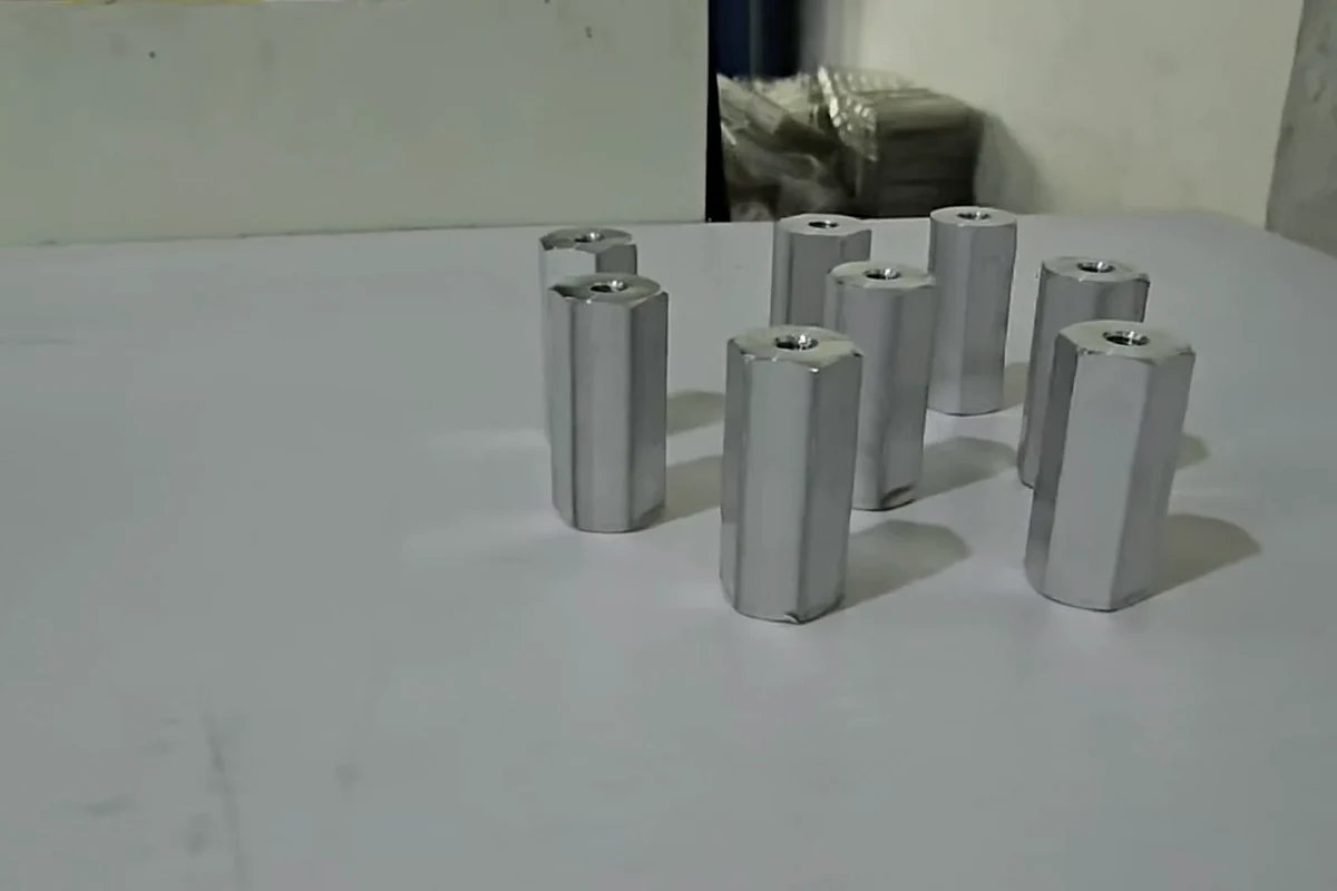
Realistic CNC tolerance ranges
| Feature | Planning range | What changes the result |
|---|---|---|
| General milled dimensions | ±0.05 mm is a practical routine target | Part size, setup count and thermal stability |
| Selected bores or turned diameters | ±0.01 mm may be achievable | Finishing pass, stable stock, tool control and dedicated gauging |
| Position and profile | Set from function and datum structure | Fixture repeatability and datum simulation |
| Thin walls | Often wider than machine positioning accuracy | Residual stress, clamping force and measurement state |
| Coated fits | Specify the final functional size | Coating growth, masking and post-treatment measurement |
These values are quotation guidance, not a universal capability claim. Separate functional characteristics such as bearing fits, sealing faces and aligned holes from nonfunctional envelope dimensions. Require first-article evidence for the critical set, then use an agreed sampling plan or capability study for repeat production.
Practical buyer scenario
A bearing bore may need a controlled finishing pass and bore gauge, while the outer cosmetic envelope can use a general tolerance. This concentrates control where assembly risk exists.
Topic-specific review checklist
- Mark functional and nonfunctional dimensions separately
- Define datums and how they will be simulated
- State whether dimensions apply before or after finishing
- Agree the instrument and reporting resolution for each CTQ
- Define first-off, in-process and final sampling
- Set a reaction plan for drift or nonconformance
Frequently asked questions
Can every dimension be ±0.01 mm?
Usually not economically, and sometimes not physically, across different sizes and geometries. Tighten only functional features.
Does a CMM guarantee accuracy?
No. Programming, fixturing, datum alignment, probe qualification and environment still matter.
Should tolerances apply before anodizing?
State this explicitly; coating growth can affect fits and threads.
What data should I request?
First-article results and, for repeat production, trend or capability data on selected critical features.
Sources and further reading
Discuss this drawing requirement with WEKO before releasing material or committing the production route.