


Start with the heat path
External fins are only one part of a motor assembly’s thermal path. Identify the heat source, housing contact conditions, airflow and allowed temperatures before selecting a fin arrangement. Additional surface area does not guarantee a proportional improvement in cooling. The product designer should evaluate the complete thermal system, including interfaces and installation constraints, rather than treating a visually dense fin pattern as evidence of performance.
Check cutter access between fins
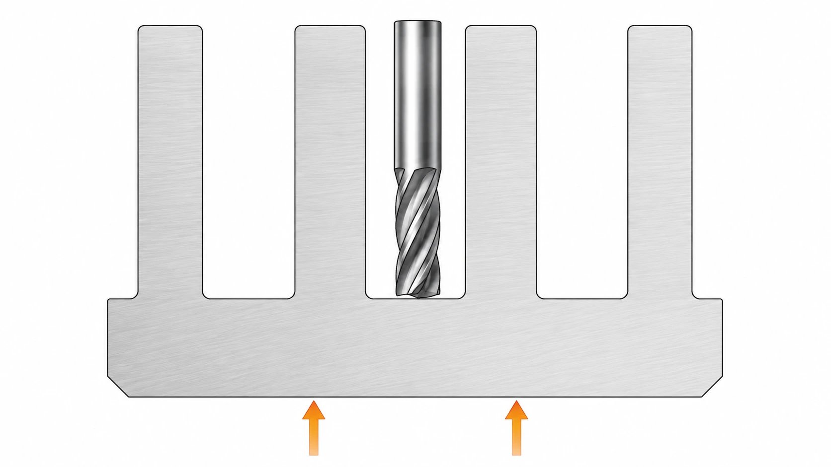
Narrow, deep channels can require slender tools with long reach. That combination affects rigidity, chip evacuation, surface quality and cycle time. Ask the machinist to review the channel width, depth and entry direction together. Where the thermal design permits, a wider accessible channel or a less demanding depth can reduce manufacturing difficulty without changing the overall mounting interfaces.
Give thin fins support
A tall thin fin can vibrate during machining or deform during handling. Review thickness, height and unsupported length as a group, including any local interruptions. A fin that can be cut once may still be difficult to produce consistently. Discuss the machining sequence and workholding before finalizing the geometry, and reserve appropriate support around clamping regions and important bearing or mounting features.
Use root geometry deliberately
A practical radius at the base of a fin can support tool access and reduce an abrupt geometric transition. Its dimensions must still fit the thermal and packaging design. Avoid specifying sharp internal corners unless the function requires them and an appropriate process is planned. Define edge conditions separately so removal of sharp handling edges does not turn into uncontrolled thinning of the functional fins.
Validate coating and installed performance
Fin channels can be difficult to coat and inspect uniformly. Agree finish coverage, masking and any cosmetic limits in the recessed areas, with the processor’s input. Evaluate the housing in its installed orientation and airflow condition. If the prototype uses a different coating, material or contact interface from production, document the difference before using its thermal result to release the production design.
Approval checklist and evidence
| Review item | Decision to make | Evidence to retain |
|---|---|---|
| Thermal duty | Establish heat input and actual installation conditions. | Thermal assessment using the intended contact interfaces. |
| Machining access | Review cutter width and reach within fin channels. | Supplier feedback on a production-intent tool route. |
| Stiffness | Assess vibration and deformation of unsupported fins. | Trial results and acceptable handling provisions. |
| Final condition | Check finish coverage and installed thermal behavior. | Documented production configuration and validation results. |
Worked review example
Illustrative scenario: a housing drawing adds deeper, more closely spaced fins while keeping the outer envelope unchanged. The nominal surface area rises, but cutter reach increases and airflow between fins may change. A joint review compares the proposed design with a shallower, more accessible version using manufacturing estimates and thermal evidence. The choice should follow those results; no universal fin spacing or guaranteed temperature reduction can be inferred from this example.
Information for the engineering review
- Heat source and installation airflow
- Channel depth, width and tool reach
- Fin stiffness and clamping zones
- Root radius and handling edges
- Final finish and thermal validation
Discuss this requirement with WEKO using the controlled drawing, the relevant mating interfaces and the review information above. Identify the decision that needs confirmation and the acceptance evidence expected with the first parts.
Sources and further reading
Frequently asked questions
Are more fins always better?
No. Airflow, conduction and manufacturability must be assessed together.
Can the supplier choose fin spacing?
They can propose manufacturing changes; the product designer must approve the thermal and functional effects.