


Separate location from clamping
Bolts normally provide clamping force, while a locating arrangement establishes a repeatable position. Decide which features perform each function in the motor assembly. Clearance bolt holes alone may not deliver the required bearing alignment. Conversely, adding tight pins everywhere can make an assembly difficult to build. Define the locating concept around the actual functional relationship between the end cover and housing.
Review restraint across the assembly
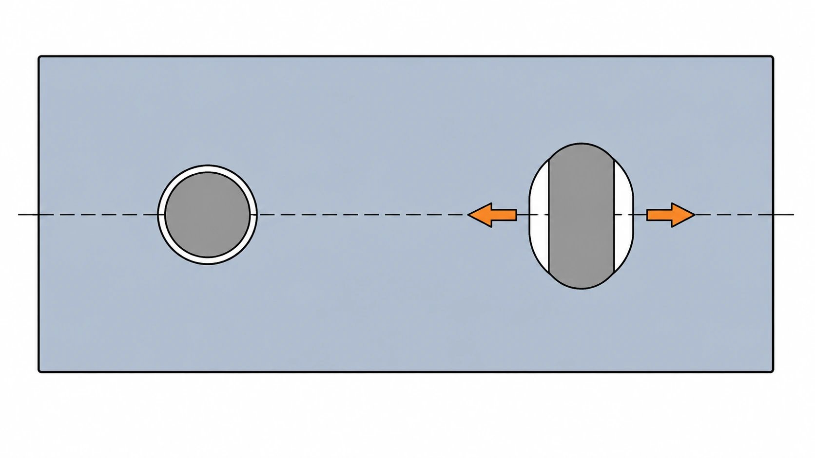
Two closely fitted round pins can overconstrain an assembly when hole spacing varies or mating components expand differently. A relieved locating element or another suitable arrangement may accommodate the intended direction of freedom. The exact solution depends on loads, service and required accuracy. Review the complete constraint scheme with the designer rather than applying a preferred pin layout without checking what each contact controls.
Dimension the mating relationship
Specify pin and hole size limits, engagement, location and the relevant datum references. Include the purchased pin specification and any retention requirement. Location tolerance affects whether two otherwise acceptable parts can assemble together, so inspect it separately from hole diameter. Keep the same functional datum interpretation across the housing, end cover and inspection plan to avoid contradictory acceptance results.
Plan installation and service
Provide appropriate entry features and access for the selected installation method. Determine which component retains the pin and how the assembly can be separated without damaging a bearing seat or sealing face. Blind holes may need an approved venting or assembly provision depending on the arrangement. Installation force is useful process information, but it should not substitute for an approved dimensional and retention specification.
Test interchangeability with representative parts
Use identified parts from a production-intent process to evaluate the locating design and assembly method. Avoid validating only one hand-matched pair if production requires interchangeability. Record the condition of pins and holes after assembly and disassembly when service matters. Changes to hole-making sequence, coating or pin source should be assessed against the approved interface and the resulting alignment evidence.
Approval checklist and evidence
| Review item | Decision to make | Evidence to retain |
|---|---|---|
| Locating concept | Assign each contact a defined constraint function. | Assembly review separating location from clamping. |
| Mating limits | Check pin size, hole size and positional relationship. | Complete tolerance assessment of the paired interfaces. |
| Installation | Define retention side and approved assembly access. | Representative installation and removal evidence. |
| Interchangeability | Check independently produced parts in intended combinations. | Identified pilot pairs and functional alignment results. |
Worked review example
Illustrative scenario: two end covers pass individual hole-diameter checks but require force when swapped between housings. The investigation finds that the report did not evaluate the spacing and location of the locating holes in the functional datum system. The response is to inspect the mating relationship and review the restraint concept. Enlarging both holes without engineering approval would change the locating function and might trade the assembly problem for an alignment problem.
Information for the engineering review
- Clamping and locating functions
- Constraint direction and thermal movement
- Pin specification and mating limits
- Functional datum and location checks
- Installation, removal and interchangeability
Discuss this requirement with WEKO using the controlled drawing, the relevant mating interfaces and the review information above. Identify the decision that needs confirmation and the acceptance evidence expected with the first parts.
Sources and further reading
Frequently asked questions
Can bolts replace locating pins?
Only if the designed bolted interface provides the required location and repeatability.
Should both pins always be press fits?
No. Retention and mating fits depend on the locating arrangement and which component is intended to hold each pin.