


Confirm the joint-level interfaces
For a robot joint, check that the bearing seats, encoder mounting face and cover register refer to a consistent datum system. A lightweight pocket is useful only if it leaves enough support for those interfaces. Review tool approach around deep ribs before freezing the model, then inspect the free-state housing after roughing and finishing. The example is a design review scenario, not a claim about a completed WEKO customer project.
Start with the assembly function
Identify which surfaces locate bearings, stators, covers and shafts. Mark sealing faces, rotating clearances and the datums that control concentricity. A drone motor cover may prioritize low mass and heat dissipation, while a robot joint housing may prioritize stiffness and repeatable bearing alignment. Keep ordinary outer-envelope dimensions at economical general tolerances and reserve tighter values for the features that change assembly performance.
Review geometry against real tool access
Deep pockets, narrow slots and small internal radii require slender cutters and slower material removal. Provide access from practical spindle directions and avoid hidden features that create another setup unless they are functional. Uniform wall thickness reduces movement during roughing and finishing. If a rib or boss interrupts tool access, ask whether a small geometry change can permit a shorter, stiffer cutter.
Control bearings, shafts and thermal interfaces
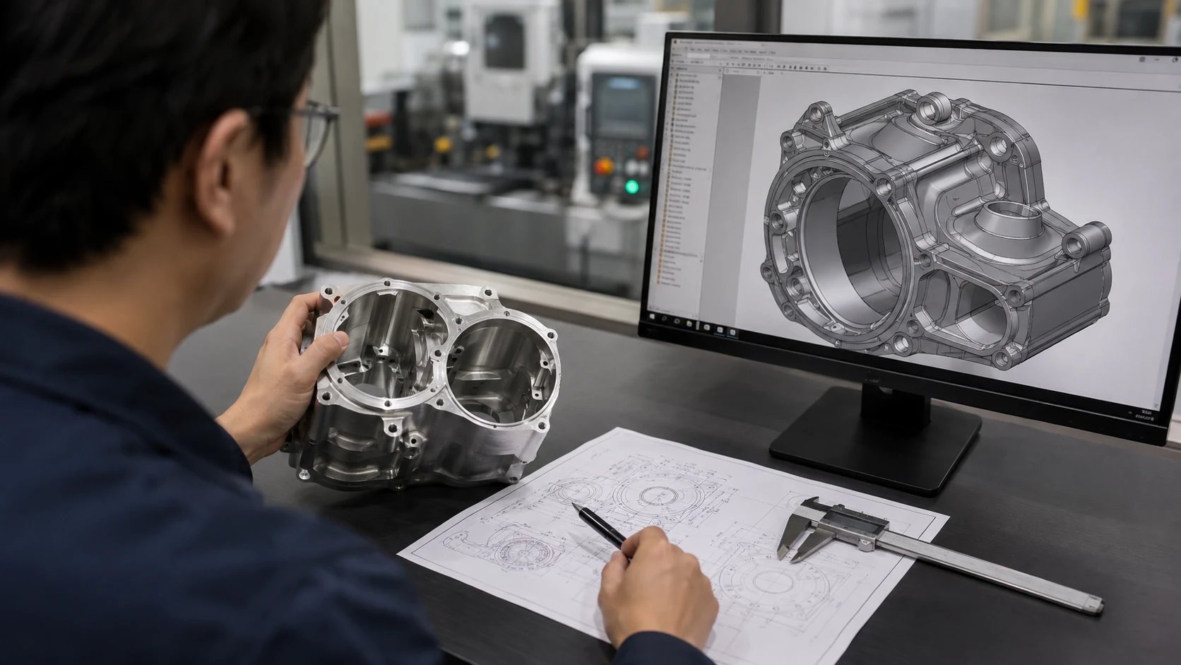
Define bearing seats with the fit, surface texture and datum relationship needed by the assembly, not only a nominal diameter. Shaft shoulders and retaining features need enough tool clearance for clean turning and inspection. For housings that conduct heat, state the contact surface, flatness requirement and permitted finish. Treat anodizing or coating growth explicitly on fits, threads and grounded contact areas.
Plan inspection before design freeze
A feature is not well controlled if the supplier cannot repeatably locate and measure it. Match bores to suitable bore gauges or CMM strategies, and avoid datum schemes that are inaccessible after machining. Define first-article evidence for the critical characteristics and a lighter sampling plan for stable repeat production. DFM should occur before design freeze and again before fixtures or production tooling are committed.
RFQ checklist
- Assembly function and critical interfaces
- Material, temper and finish
- Bearing and shaft fit requirements
- Datum scheme and rotating-feature relationships
- Wall thickness, ribs and tool access
- Prototype and production quantities
- Required first-article evidence
Illustrative example: redesigning a robot joint housing
A compact joint housing arrived with deep pockets, 1 mm internal radii and bearing bores dimensioned from unrelated outside faces. The combination required long cutters, three setups and a difficult inspection alignment. The review changed nonfunctional corner radii to 3 mm, established the primary bearing bore and mounting face as functional datums, and opened one pocket for direct tool access. The revised route used shorter tools and a more repeatable fixture while preserving the assembly envelope. This is the purpose of DFM: remove manufacturing cost without weakening the function.
What to send for a useful DFM review
Send the 3D model and controlled 2D drawing together so geometry and requirements can be compared. Include annual volume, prototype quantity, mating components, load direction, operating temperature and cosmetic zones. Identify dimensions that can change and those already frozen by the surrounding assembly. If mass is critical, give the actual target instead of asking the supplier to remove as much material as possible. A good response should separate required changes, optional cost reductions and questions that need engineering approval.
Buyer decision
Approve the design when the supplier can explain the machining route, show how the functional datums will be held and measured, and separate necessary tolerances from expensive preferences. Request a marked drawing with every proposed change and its reason. Do not accept an undocumented geometry change made only in the CAM program. The released model, drawing and DFM record should agree before the first production setup begins.
Record accepted DFM changes in the released drawing, not only in email. This gives purchasing, production and inspection one controlled definition of the part and prevents an old geometry revision from returning during reorder.