


Review the final assembled stack
Evaluate the bearing shoulder, cover register and spacer together rather than tightening all three dimensions independently. In a simple worst-case stack, three ±0.02 mm contributors can produce ±0.06 mm of variation. Check the resulting preload or clearance against the bearing and assembly requirements. Use that analysis to allocate tolerances and select the final inspection condition, including any restraint applied to thin covers.
Separate locating features from the envelope
Bearing bores, pilot diameters and cover registers establish the rotating assembly. Their size, roundness and relationship to datums normally deserve tighter control than external walls or cosmetic pockets. Use a datum scheme that reflects how the housing is assembled and tested. Avoid locating the drawing from a surface that is unstable, unfinished or difficult to fixture.
Control coaxiality and end-face relationships
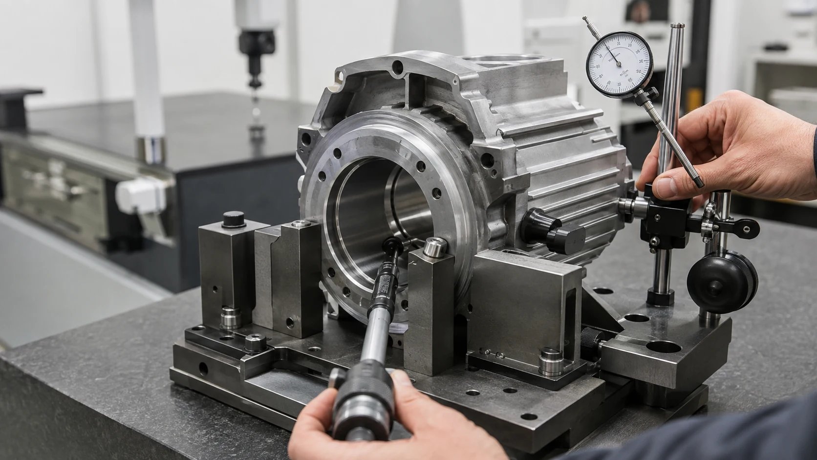
Two acceptable bore diameters can still produce poor rotation if their axes are misaligned. Use position, runout or profile controls that match the design intent rather than piling plus-minus dimensions into a tolerance stack. End covers may need a controlled pilot and face perpendicularity to prevent bearing preload or seal variation. Review how these features will be produced across setups.
Account for thin walls and finishing
Thin housings can move when clamps are released or residual stress is removed. Plan roughing, stress relief where justified, balanced stock removal and a stable finishing setup. Anodizing and powder coating change surface build and can affect fits or threads. State masking and final-size requirements so the quotation includes the correct process.
Use realistic planning values
General machined dimensions around plus or minus 0.05 mm are often economical. Selected bores or faces may reach plus or minus 0.01 mm with controlled finishing and gauging, but geometry and part size matter. These are planning ranges, not blanket capability claims. Require evidence on the functional characteristics and relax nonfunctional dimensions.
Drawing-release checklist
- Functional datum structure
- Bearing and register fits
- Coaxiality, runout or profile intent
- Thin-wall and clamping risk
- Finish growth and masking
- Agreed measurement method
Illustrative example: bearing preload caused by an end-cover stack
A motor end cover had acceptable pilot diameter, face thickness and bearing-seat depth when each was checked separately. During assembly, their combined stack reduced axial clearance and created inconsistent preload. The drawing was revised to control the functional distance directly from the mounting face, with a clear datum structure and one inspection method. Nonfunctional outside dimensions were relaxed. Controlling the assembly result was more reliable and less expensive than tightening every contributor.
How to communicate tolerance priorities
Mark critical characteristics and explain the failure mode they prevent, such as rotor rub, seal leakage or bearing misalignment. Apply general tolerances only to dimensions that truly can share them. For special fits, state the mating part, fit intent, surface texture and final condition after coating. Ask the supplier to identify setup changes and measurement limitations during quotation. If the part is thin, agree whether it is measured free state or restrained. This prevents a technically conforming report from hiding a part that will not assemble.
Buyer decision
A defensible drawing tells the supplier where precision creates function and where ordinary process capability is sufficient. Review tolerance stacks using the mating components, not the housing alone. Confirm coating state, measurement restraint and temperature assumptions in writing. Before volume release, inspect a production-intent pilot lot and evaluate assembly performance alongside the dimensional report. That evidence is more useful than applying one severe tolerance to the entire part.
When a tighter value is proposed, ask what functional risk it controls, how it will be produced, how it will be measured and what it adds to price. Keep the tolerance only when those answers support the assembly.