

 Weko Quality Team
WEKO QUALITY LAB · A report-reading exercise for buyers and engineers
A coordinate measuring machine report is evidence about a particular part measured in a particular way. A green cell helps you scan it. Before accepting a first article or repeat batch, you still need to know which drawing revision the CMM program used, how the part was aligned, what the number means, and which decision rule turned the number into a pass or fail.
Start with a practical example. A bore on a CNC machined part is allowed to measure from 32.000 to 32.025 mm. The CMM report says 32.023 mm. The indicated value is 0.002 mm below the upper limit. If the stated expanded uncertainty for that measurement is ±0.004 mm, a displayed pass needs more explanation. The result is close enough to the limit that the supplier and buyer should consult the decision rule they agreed for the job.
Read the result and the rule together
The chart shows three readings for the same illustrative bore. The horizontal bars show each indicated value plus and minus the stated expanded uncertainty. The upper specification limit is the dashed line. The lower limit is 32.000 mm and lies outside the portion of the axis shown. The bounds help explain how a decision can change near a limit. They do not represent the full probability distribution or specify a default decision rule.
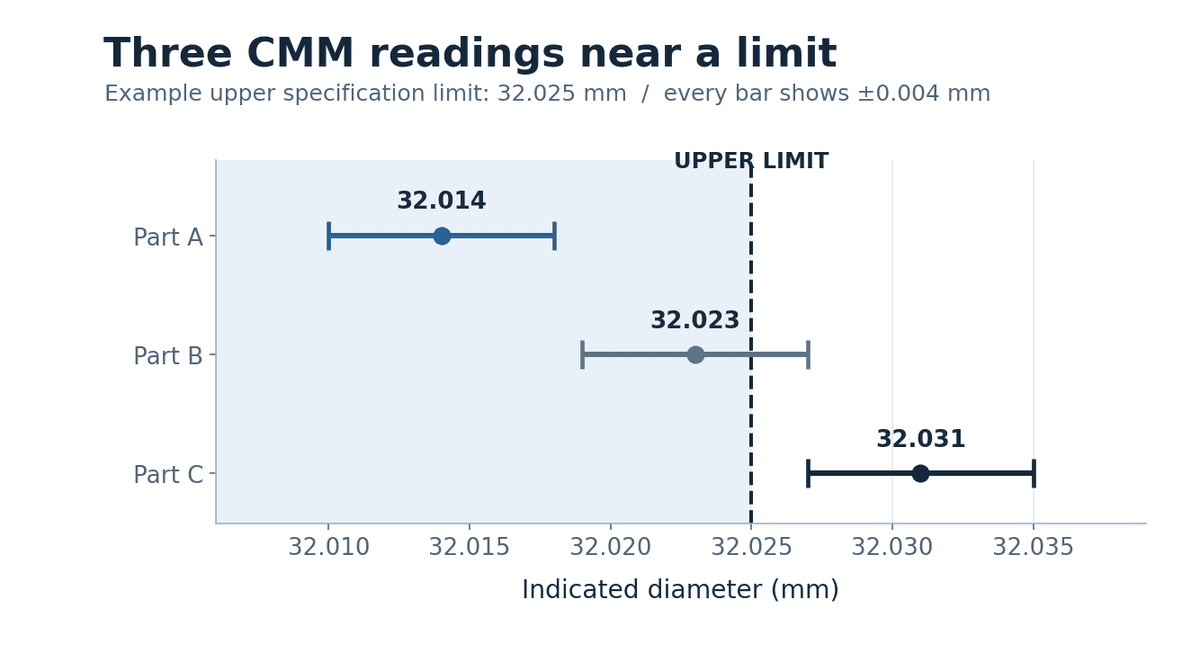
All numbers are illustrative. The uncertainty values do not describe WEKO’s CMM capability, and the chart does not establish a disposition for any production part.
| Part | Indication and interval | What you can see |
|---|---|---|
| A | 32.014 mm; 32.010–32.018 mm | Shown interval is inside both limits |
| B | 32.023 mm; 32.019–32.027 mm | Indication is inside; interval crosses the upper limit |
| C | 32.031 mm; 32.027–32.035 mm | Indication and shown interval are above the upper limit |
A simple acceptance rule compares the indication directly with the specification limits. A different rule may move an acceptance limit inward using a guard band to manage the risk of accepting a nonconforming part. The size of the guard band and treatment of results outside the acceptance band depend on the applicable rule and contract. Do not apply the chart’s full uncertainty interval as an automatic rule. ISO 14253-1 addresses decision rules within its scope, and NIST’s decision rule guidance explains why this decision depends on the risk being managed.
Check the report header before the coloured cells
Match the part number, drawing revision, units, material or finish state where relevant, inspection date, sample ID and lot to the shipment. If the report covers three serial numbers and the shipment contains 100 parts, it describes those measured samples. It does not establish that every unit was checked. A first article inspection report can also include drawing characteristics, material and process records, and sign-offs that do not appear in a CMM export. Ask purchasing and quality to agree which evidence is expected before the order.
Next find a reference back to the drawing. A ballooned drawing gives every characteristic a number, so the inspector can line up a measured result with the specified feature. Compare the feature number, nominal, lower and upper limits, actual, deviation and units. If the nominal is 32.000 and the indicated bore is 32.023, the deviation from nominal is +0.023 mm. That deviation is not the remaining margin; the margin to the upper limit is 0.002 mm. Ask the supplier what any output column called “error,” “deviation” or “out of tolerance” is calculated against.
Check the datum reference frame and the probing strategy
Coordinates come from an alignment. A part can look better on a best-fit alignment to its CAD model than it does when seated on the primary and secondary datums identified on the drawing. For a pattern that locates an assembly, ask which features established the datum reference frame, in what order, and whether any material boundary modifier applies. If the subcontract report leaves that blank, request the alignment record or the relevant setup excerpt before trying to reconcile the result with another lab.
CMM measurement also depends on how the probe samples the feature. A diameter fitted from a single ring near the opening may tell a different story than probing at several depths when a bore is tapered or lobed. Different fitting criteria can produce different numbers from related point sets. Check the characteristic actually specified, the measurement plan, and the agreed fit or form evaluation. Use the physical mating requirement to decide whether a CMM measurement, a functional gauge, or both are appropriate. The UK National Physical Laboratory’s CMM measurement strategies guide discusses sampling, alignment, temperature and surface condition.
What the equipment certificate does and does not tell you
A current equipment calibration or verification record helps establish that the machine is maintained for its intended work. It does not give the uncertainty of every characteristic it measures. A thin part that deflects in a fixture, a recessed feature requiring a long stylus, and a large bore still cooling after machining present different problems on the same machine. When the margin is small, ask for evidence that applies to the actual feature and method. This could include an uncertainty estimate for the task, a repeatability check under the agreed setup, or a comparison against a suitable reference. Repeatability helps explain variation on repeat measurements; repeating the same setup does not reveal every source of bias.
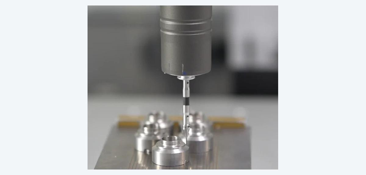
WEKO inspection reference. Probe access and how the part is seated affect what the report can tell you about the actual drawing feature.
Resolve a near-limit result without losing traceability
1. Isolate the actual sample. Record its ID, batch and current finish state. Keep the part and the original result available.
2. Read the controlling requirements. Confirm the revision, characteristic, limit, units, sampling plan and decision rule. Check whether uncertainty is applicable to that result and how it was assessed.
3. Compare like measurements. Ask for the alignment, technique and report configuration. If results differ between labs, compare probe strategy, fit method, environment and part temperature before assuming the part changed.
4. Write down the disposition. Decide whether the evidence supports release, remeasurement under an agreed method, rework, or a formal concession from the design owner. Preserve all results, not just the more favourable one.
For recurring production, use the first order to agree which features will be measured on subsequent lots and which require notification if the material, finish, fixture or measurement program changes. A good report makes future comparisons possible because the feature numbers, sample identity and measurement method remain traceable.
If a report is disputed, send a small packet instead of a screenshot of a red or green cell: the drawing excerpt, sample ID, exact measured value with units, measurement method, decision rule and any assembly evidence. Ask the inspector to resolve one disputed characteristic in writing. Once resolved, carry that decision into the next inspection plan so it does not have to be relearned with every batch.
WEKO’s quality and inspection page explains which manufacturing records can be scoped in a quote. When you send a drawing for review, mark the critical characteristics and state the report, sample size and decision rule you need. Agree those details before machining so inspection answers the question that controls release.