


Write the reaction rule beside the check
For a sealing connector, an accepted outer diameter does not establish a sound sealing face. Include the face geometry, surface condition and any approved leak test required by the product design. When a check fails, identify the last accepted piece, hold the affected interval and record the disposition. Keep the report tied to actual sample identifiers so a measurement cannot be copied across unmeasured parts.
Build a characteristic map
List each interface and the failure it can create. A shaft bearing journal may require diameter, roundness and runout to a functional datum. A sleeve may need bore size, wall thickness and coaxiality. A connector can depend on thread form, sealing face and cleanliness. This map prevents a long report of easy dimensions from replacing evidence on the few characteristics that determine assembly.
Match instrument to feature
Micrometers are efficient for accessible diameters, while air gauges or bore gauges can be better for repeated internal-size checks. Optical systems help with profiles and edge features. A CMM supports datum-based position and profile but still depends on fixturing, probing strategy, temperature and program control. Confirm resolution and uncertainty are appropriate for the tolerance.
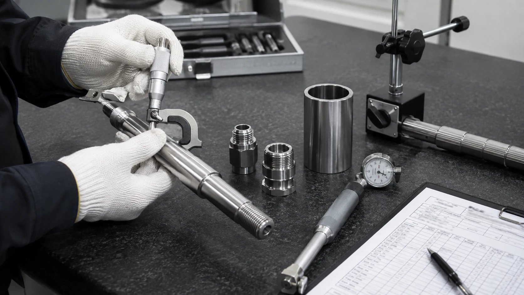
Define sampling and reaction
Inspect the first piece after setup and after significant tool or program changes. During production, choose frequency from risk, process stability and tool wear rather than copying one percentage to every feature. Record what happens when a result approaches the limit, not only after it exceeds the limit. Segregation, tool correction and re-verification should have named owners.
Make reports traceable
The report should identify part number, revision, lot, instrument, date and inspector. Link material and outside-process evidence to the same lot. For critical rotating or sealing components, retain raw values rather than only a pass mark. A buyer should be able to connect the report to the shipped parts without relying on filenames or memory.
Inspection-plan checklist
- Functional characteristics and datums
- Instrument and method for each CTQ
- First-off and in-process frequency
- Tool-wear and drift reaction limits
- Lot and report traceability
- Final release authority
Illustrative example: a connector that passed diameter inspection but leaked
A stainless connector met its outside diameter and thread gauge checks, yet the assembly leaked during pressure testing. The missing controls were sealing-face flatness, surface condition and the relationship between the face and thread axis. The revised plan added an optical face check, a datum-based runout measurement and protected packing that prevented contact scratches. The lesson is that inspection quantity is not inspection quality: the plan must measure the features that create the seal.
Capability, calibration and measurement agreement
For repeat production, use actual measurement values to assess centering and spread rather than relying only on pass marks. Confirm that gauges are calibrated, suitable for the tolerance and used in the same temperature condition defined for acceptance. When buyer and supplier use different methods, correlate them on the same sample set before a dispute occurs. Photographs can document appearance and setup, but they do not replace dimensional data. The purchase order should state which report is required with each lot and how long records must be retained.
Buyer decision
Approve an inspection plan only when every critical characteristic has a named method, frequency, record and reaction. Ask for a sample report before production so units, datum references and identifiers can be corrected early. If the feature cannot be measured reliably after completion, add an in-process check. Keep the final report concise enough to review, but complete enough to connect every result to the shipped lot.
For repeat orders, review trends from earlier lots before setting the next sampling plan. Stable history can justify efficient inspection, while drift, tool changes or supplier changes should trigger additional verification until capability is demonstrated again.