


Identify the axis that matters
Runout is meaningful only relative to a defined datum axis. Start with the surfaces that locate the shaft in the motor, usually its bearing journals or other specified locating features. A measurement between centres can differ from one based on the bearing journals if the centre holes do not represent assembly location. Name the intended datum features on the drawing and agree how inspection will simulate them.
Distinguish size from rotational variation
A micrometer checks local diameter but does not establish that a journal is coaxial with another journal. A dial indicator reading during rotation combines the effects visible at its contact location. Do not interpret that reading automatically as a pure eccentricity value; roundness and setup errors may contribute. Decide whether circular runout, total runout or another geometric requirement best expresses the functional relationship, using the chosen drawing standard.
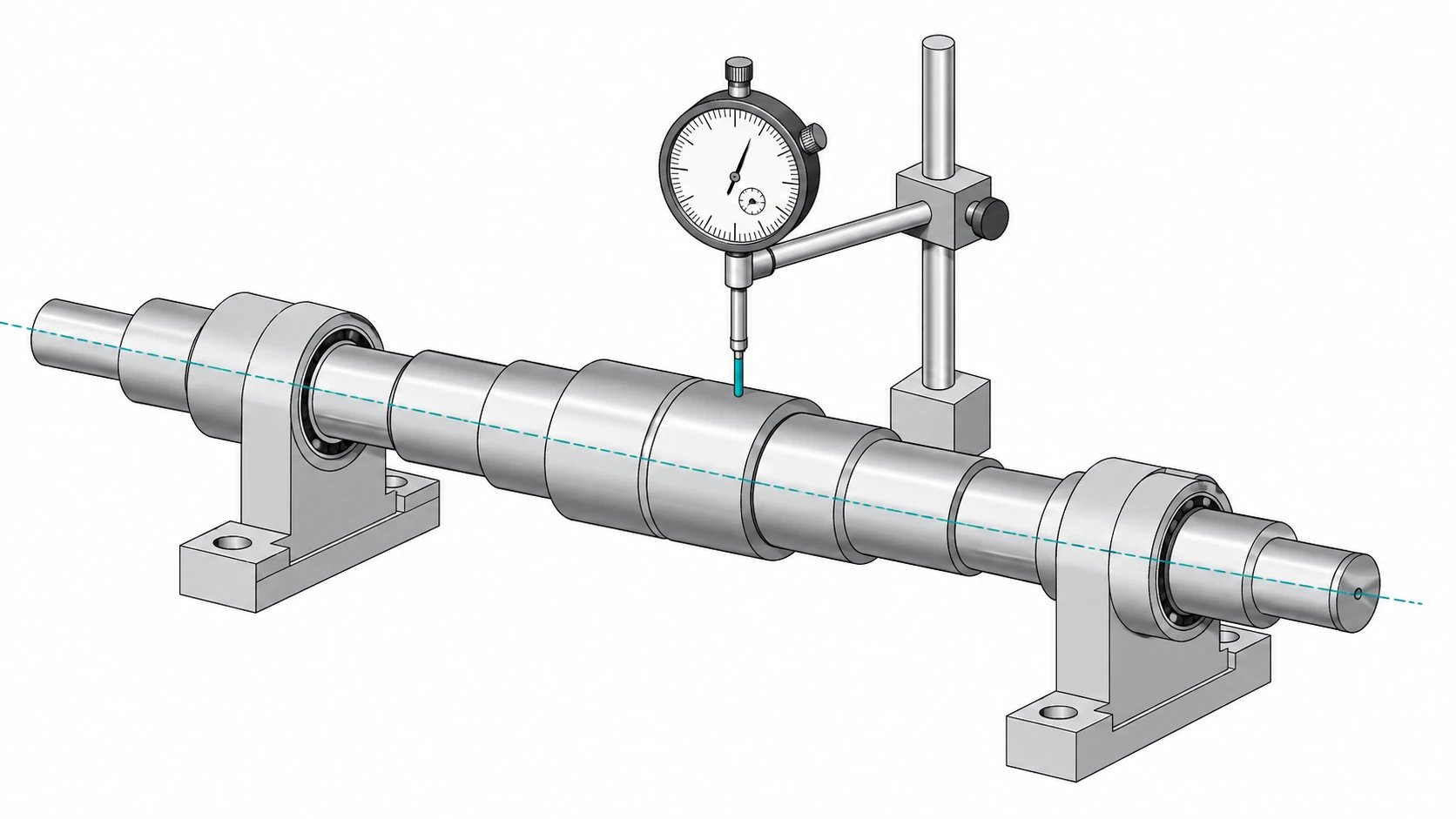
Make the support repeatable
Specify support surfaces, contact locations and restraint. Dirt, burrs or inconsistent seating on V blocks can produce a changing indication that looks like a machining defect. Keep the indicator orientation and contact force suitable for the task, and rotate the shaft without pushing it against the probe. A photograph of the setup is useful when it accompanies the datum definition and the written measurement method.
Inspect at useful axial locations
Check the locations that influence bearing alignment, seal operation and coupling behavior. A reading at one short journal does not characterize a long shaft or an adjacent seal land. Where the requirement covers a surface length, define the sampling or scanning strategy. Record the position of each result so a taper, bent section or local defect is not hidden inside one reported maximum number.
Separate machining and handling causes
A shaft may leave turning in good condition and later bend during heat treatment, straightening, transport or assembly. Place inspection after the operations that can affect its final state. Use protected supports and avoid contact damage on datum journals. If a problem appears, compare identified parts across process stages before changing the turning offsets; an upstream correction cannot reliably compensate for an uncontrolled downstream distortion.
Correlate the supplier and buyer methods
Measure the same identified shafts with both agreed setups before production acceptance depends on small differences. Include parts spanning the observed range, and record repeated readings without selecting only the most favorable value. Investigate systematic offsets before deciding which lot is acceptable. The useful outcome is a method that gives consistent decisions, supported by appropriate calibration and uncertainty, rather than a competition between instrument brands.
Approval checklist and evidence
| Review item | Decision to make | Evidence to retain |
|---|---|---|
| Datum journals | Choose the actual functional axis and support arrangement. | Drawing references matched to the inspection setup. |
| Indicator path | Specify the surface and axial position being evaluated. | Measurement instructions showing contact direction and location. |
| Form effects | Distinguish surface variation from axis alignment requirements. | Separate results for the specified geometric characteristics. |
| Repeatability | Recheck after removing and replacing the inspected shaft. | Recorded setup variation before production acceptance. |
Worked review example
Illustrative scenario: a shaft passes diameter checks at both journals but shows 0.035 mm total indicator variation at the seal land. Repeating the check after cleaning the supports changes the reading to 0.018 mm. The difference shows why setup control must be resolved before assigning all variation to the part. Neither number establishes acceptance until the drawing limit, datum simulation and measurement uncertainty are known. Retain the original observations and corrected setup record instead of erasing the first result.
Information for the engineering review
- Functional datum axis and journal identification
- Runout characteristic and covered surface length
- Support, probe orientation and rotation method
- Final process stage at which acceptance occurs
- Correlation samples and response to disagreement
Discuss this requirement with WEKO using the controlled drawing, the relevant mating interfaces and the review information above. Identify the decision that needs confirmation and the acceptance evidence expected with the first parts.
Sources and further reading
Frequently asked questions
Is runout the same as concentricity?
No. They are different geometric concepts and must be specified using the selected drawing standard.
Should every shaft use the same indicator setup?
No. The setup must represent its datum arrangement, stiffness and inspection requirement.