


Recognize the workholding problem
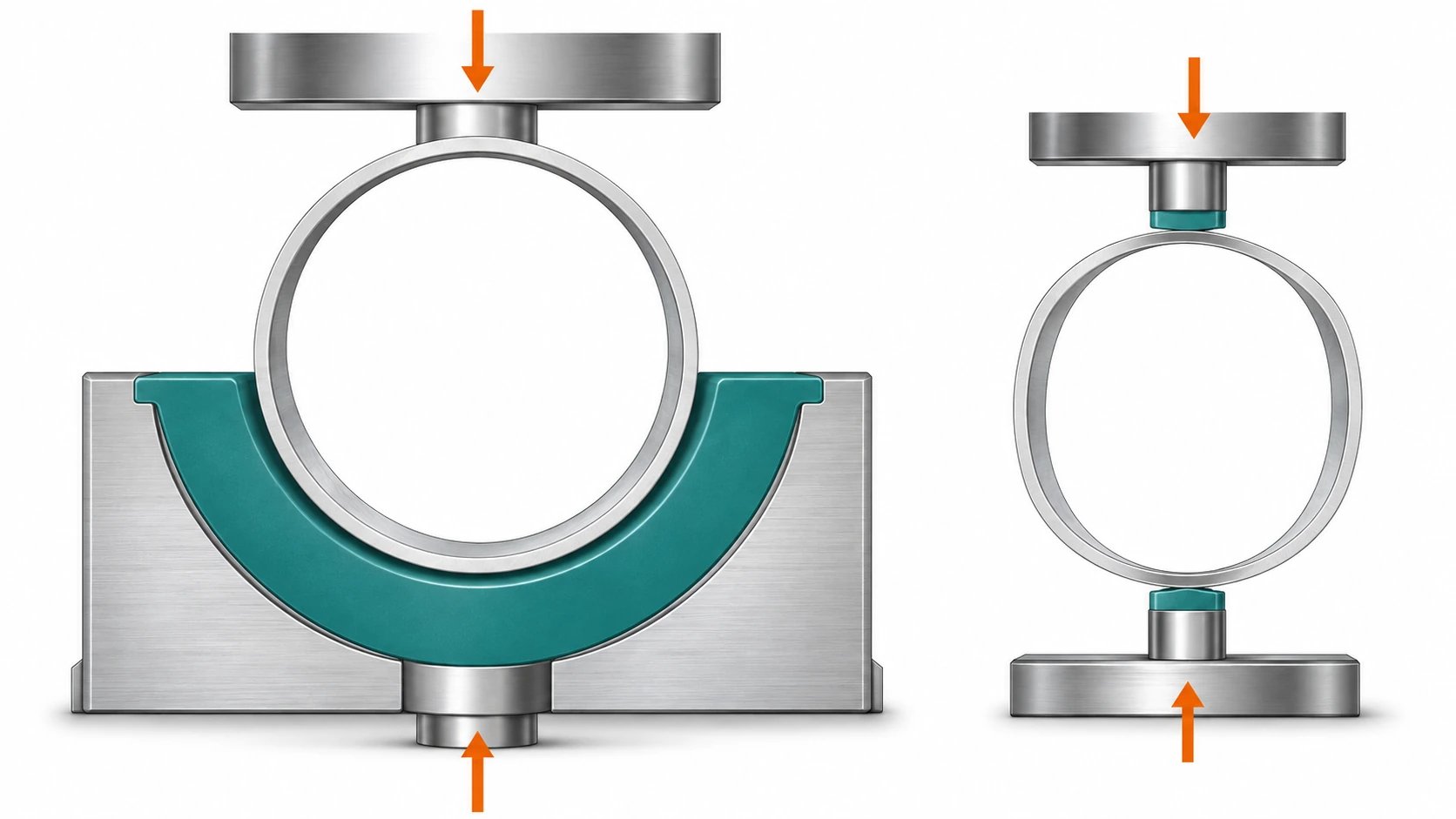
A thin housing can deform under clamping loads even when the machine follows its programmed path accurately. Once released, the component springs toward a different shape and the measured bore or flange may move. Review wall height, interrupted pockets, bosses and open sections before selecting a fixture. The weakest local region often determines the suitable holding strategy more strongly than the overall part diameter or nominal machine precision.
Distribute contact without hiding errors
Broad soft jaws or dedicated supports can spread load, but more contact is not automatically better. A fixture that forces a warped housing into shape can hide an unacceptable free-state condition. Define the intended locating surfaces and separate locating from clamping functions where practical. The fixture should establish repeatable position while using only the force needed to resist cutting loads under the approved route.
Keep support through roughing
Plan the order in which walls, floors and ribs become flexible. Leaving temporary stock or balanced support during roughing can help, provided the final removal operation remains accessible. Avoid removing all supporting material early and then using higher clamp force to compensate for a weak structure. Discuss roughing allowances, intermediate checks and the final pass with the shop before freezing features that constrain tool access.
Control the conditions of inspection
A free-state flatness requirement and an assembled restrained requirement are different acceptance conditions. State the intended condition explicitly, including any defined fastening or support arrangement. Measure after the part has reached the specified thermal condition and after relevant finishing. A report that omits restraint can allow supplier and buyer to produce different results on the same housing while both believe they followed the drawing.
Validate the fixture through normal variation
Use representative stock and more than one part when approving the setup. Check that expected wall and blank variation do not change how the part seats. Include an ordinary unload and reload sequence, because a fixture adjusted carefully around one sample may not locate the next piece consistently. Record clamp settings, support locations and any consumable jaw features needed to reproduce the result.
Treat changes as process changes
A new soft-jaw set, a different stock condition or a changed pocketing sequence can affect distortion. Identify which changes require a first-off check or a renewed pilot. Store the approved fixture drawing and setup instructions with the manufacturing revision. When a bore drifts, inspect clamping, tool wear and material condition systematically rather than correcting size repeatedly without understanding why the free-state geometry is moving.
Approval checklist and evidence
| Review item | Decision to make | Evidence to retain |
|---|---|---|
| Wall support | Spread support across a suitable noncritical surface. | Reviewed fixture contact map and clamping sequence. |
| Cutting sequence | Balance material removal around the flexible geometry. | Production-intent trial with identified tool and fixture. |
| Released shape | Measure after the specified restraint is removed. | Free-state or restrained results clearly distinguished. |
| Finish route | Assess treatment and handling after the last cut. | Final dimensions and damage check before release. |
Worked review example
Illustrative scenario: a housing bore measures round while held in three narrow jaws but becomes oval after release. Reducing the cutting feed does not solve the problem because the fixture is already deforming the part before cutting. A trial with broader contact and a revised roughing sequence may improve the result, but it must be evaluated on released parts. Compare free-state measurements from the original and revised setups under the same method before accepting the change.
Information for the engineering review
- Minimum wall and local stiffness map
- Locating surfaces and clamp-contact locations
- Roughing sequence and temporary support stock
- Free-state or restrained acceptance condition
- Fixture revision and reload repeatability
Discuss this requirement with WEKO using the controlled drawing, the relevant mating interfaces and the review information above. Identify the decision that needs confirmation and the acceptance evidence expected with the first parts.
Sources and further reading
Frequently asked questions
Does a more accurate machine solve thin-wall distortion?
Machine capability helps, but workholding, residual stress and thermal conditions still affect the released part.
Can inspection use the machining fixture?
Only if that restraint matches the agreed acceptance condition and does not hide the relevant error.