


Define why the insert is needed
An insert may improve serviceability, support repeated assembly or restore a damaged thread, but those are different design situations. Identify the required fastener, loading, installation cycles and environment before choosing an insert family. Do not add an insert solely because aluminum is assumed to be unsuitable for every direct thread. Compare the available wall thickness, engagement length and assembly requirements with the selected fastening system.
Use the selected product dimensions
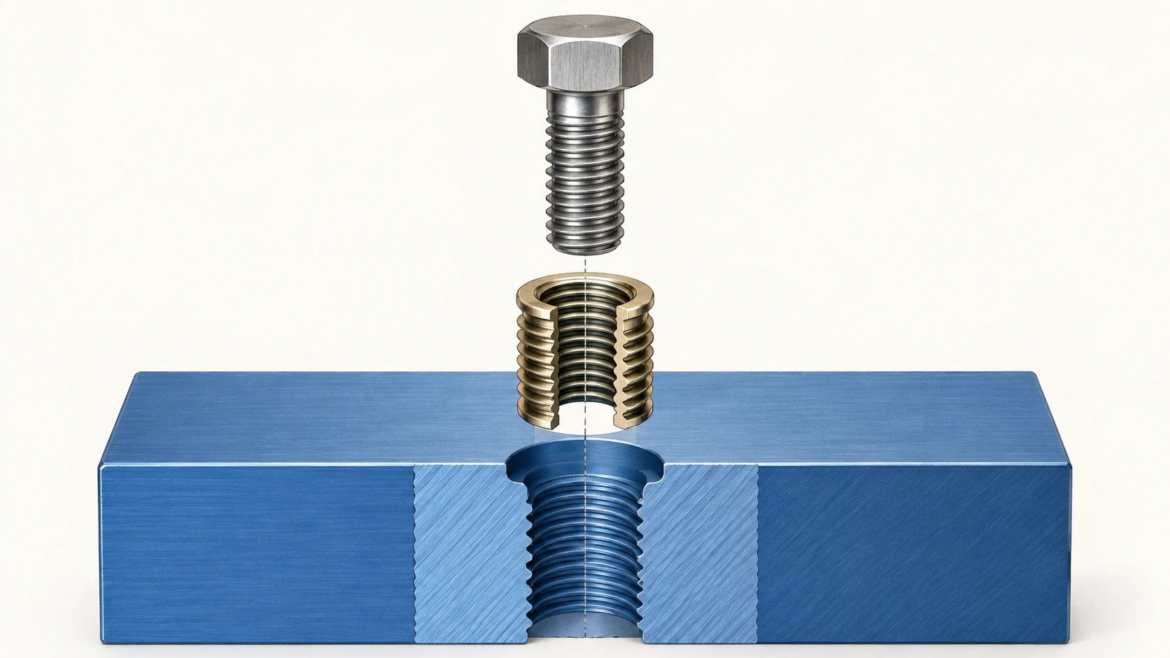
A wire insert and a solid bushing insert require different receiving-hole geometry and installation tools. Specify a complete manufacturer designation or a controlled performance specification with an approved design. Use the receiving thread, depth, lead-in and installation requirements for that product. A note that says only insert M6 leaves important dimensions unresolved and can result in a component that accepts the bolt but cannot accept the chosen insert.
Check edge distance and remaining wall
The receiving hole is larger than the final internal thread, so it removes more surrounding material. Review the distance to exterior walls, nearby bores and sealing passages. A thin boss that looked adequate for a directly tapped hole may need redesign for an insert. Account for any local forces produced during installation, and validate the boss using the applicable load case rather than relying only on nominal thread diameter.
Plan installation access and sequence
The installation tool needs an approach path, room to align and any required clearance for tang handling or locking features. Decide whether the insert is installed before or after finishing, using the product and finish requirements. Avoid allowing coating buildup or trapped debris to compromise installation. Define how an installed insert is identified and protected through later operations so a missing or damaged insert is visible before assembly.
Inspect the finished thread and retention
The receiving thread and the final installed thread are separate process checks. Confirm the inspection method after installation, including any permitted projection or recess. Where retention or repeated use is important, the designer should specify the appropriate validation or acceptance tests. Do not invent a universal installation torque or pull-out value; those depend on the insert, parent material, geometry, lubrication and test configuration.
Separate production from repair approval
A planned production insert is part of the released design. A repair insert added after a damaged direct thread may change wall thickness, alignment or service behavior. Require the authorized engineering disposition for a repair and identify the affected parts. Retain installation and inspection records so the repaired population is not mixed invisibly with components produced to the original direct-thread drawing.
Approval checklist and evidence
| Review item | Decision to make | Evidence to retain |
|---|---|---|
| Insert identity | Select the actual insert family and length. | Manufacturer specification and approved part designation. |
| Receiving geometry | Check the wall, hole preparation and engagement. | Drawing dimensions matched to installation guidance. |
| Installation | Control alignment, depth and any required tang removal. | Defined method and inspection of the completed installation. |
| Retention | Validate the property needed for the actual assembly. | Approved retention or assembly evidence for the application. |
Worked review example
Illustrative review: an aluminum cover has an M6 fastening hole beside a narrow sealing groove. The proposed insert requires a larger receiving hole that would reduce the material separating the thread from the groove. Before approving the insert, compare its actual installation drawing with a section through the cover. Possible design responses include relocating the hole, enlarging the boss or retaining a validated direct thread. The correct answer depends on the load and sealing requirements, not on insert marketing claims.
Information for the engineering review
- Reason for using the insert
- Complete insert and receiving-hole specification
- Remaining wall and distance to nearby features
- Installation tooling and finishing sequence
- Final thread acceptance and repair authority
Discuss this requirement with WEKO using the controlled drawing, the relevant mating interfaces and the review information above. Identify the decision that needs confirmation and the acceptance evidence expected with the first parts.
Sources and further reading
Frequently asked questions
Can any insert replace a damaged thread?
No. The remaining material, alignment and application must support the repair, with authorized approval.
Should the drawing specify only the bolt size?
No. It must also define the selected insert and the receiving geometry needed to install it.